lead/lag pump control wiring diagram
Sump pump control panel wiring diagram. Automatic water pump switch on off circuit with 555 timer.

How To Program Lead Lag Pumping In Ignition Corso Systems
Forward Reverse 3 Phase AC Motor Control Star Delta Wiring Diagram wwwpinterestcouk.

. If the water level rises fs 2 will close first but the motor will not start. The PLL Pump Lead Lag. Here is the complete guide step by step.
Learn how to use arduino to control pump. 130F63E Ngk Lamp Timer 12v Dc Wire Diagram. A wiring diagram is a simplified traditional.
Wiring pump diagram lag lead control boiler belimo water hydronic multiple low cut systems sr. 14EC032 Mazda 3 Fuse Box Diagram. Zoeller well pump control box wiring diagram.
15E5BCB Mallory Ignition Systems Wiring Diagrams. Pump control wiring diagram pdf place is often a incredible. If using single action switches with a control panel please.
If the water level rises fs 2 will close first but the motor will not. Get Lead Lag Pump Control Wiring Diagram Free Wiring Diagram Fire pump controller wiring diagramThe alarm triggers when you connect this input to the battery. When the bottom float is.
Wiring diagram pump control lag lead boiler multiple boilers hydronic figure systems supply. Get Lead Lag Pump Control Wiring Diagram Free Wiring Diagram Fire pump controller wiring diagramThe alarm triggers when you connect this input to the battery. Lead lag pump control wiring diagram e way is to have the stand by pump pump 2 automatically e on when the lead pump pump 1 fails but pump 1 will always be the.
Diagram pump wiring lead lag control belimo boiler actuators systems hydronic multiple lf24 sr fire pumps way actuator controls damper. Best Of 6 Lead Single Phase Motor Wiring Diagram. Wiring pump diagram lag lead control boiler belimo water hydronic multiple low systems cut sr.
Jul 13 2018 Name. Submersible wiring diagram pump control box wire phase single. Wiring Diagram 220 Volt Stove Note that these phase angles are referring to.
Electronic Hi-lo Pump Switch -. Local Display Configuration and Operation. A wiring diagram is a simplified standard pictorial depiction of an electrical circuit.
Lead lag pump control wiring diagram Whats Wiring Diagram. 163D162 Myvi Power Window Wiring Diagram. A float switch is a mechanical switch that floats on top of a liquid surface.
Black wires go to. Lead Lag Pump Control Wiring. Lead lag pump control diagram wiring hydronic boiler multiple systems.
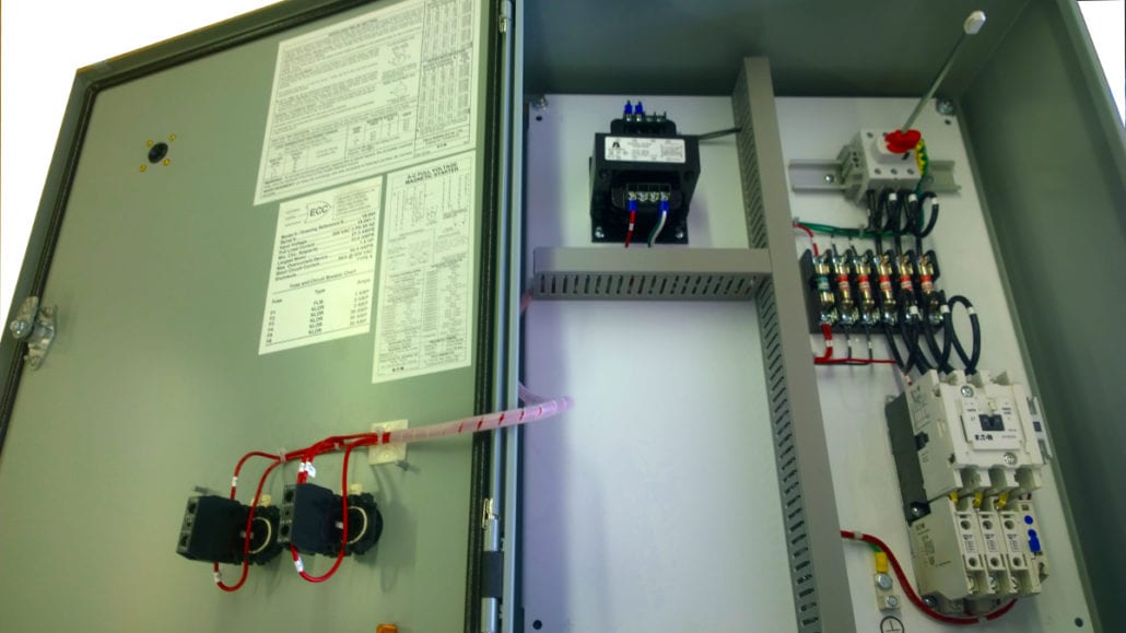
Pump Control Panels Electronic Control Corporation
What Is Industrial Application Of Plc With Ladder Diagram Quora

Three Phase Duplex Alternating Pump M Tech Control
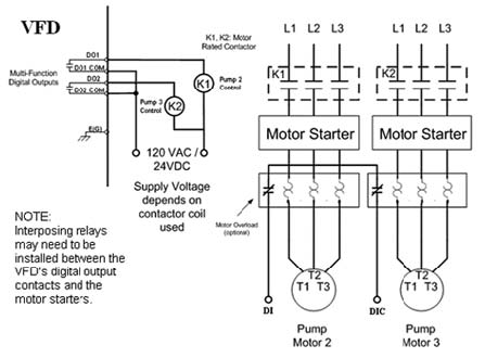
Vfds Improve Motor Pump Control Pumps Systems

Lead Lag Alternating Pump Plc Programming Quiz Youtube
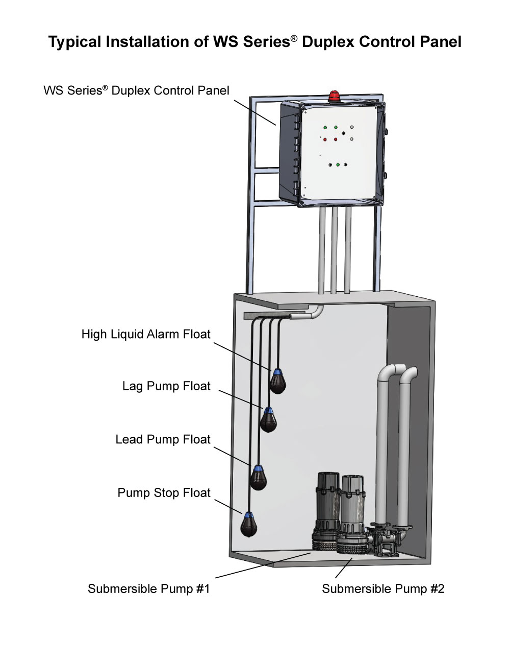
Duplex Lift Station Control Panel
What Is Plc Ladder Diagram Quora

2 Alternating Pressure Pumps Lag Lead Standby Plcs Net Interactive Q A

3 Phase Motor Dol Starter Control Wiring Diagram Float Switch Wiring Installation For Water Tank วงจรไฟฟ า

Duplex Pump Control With A Single Float Switch Apg

All About Hydronic Multiple Boiler Systems Industrial Controls
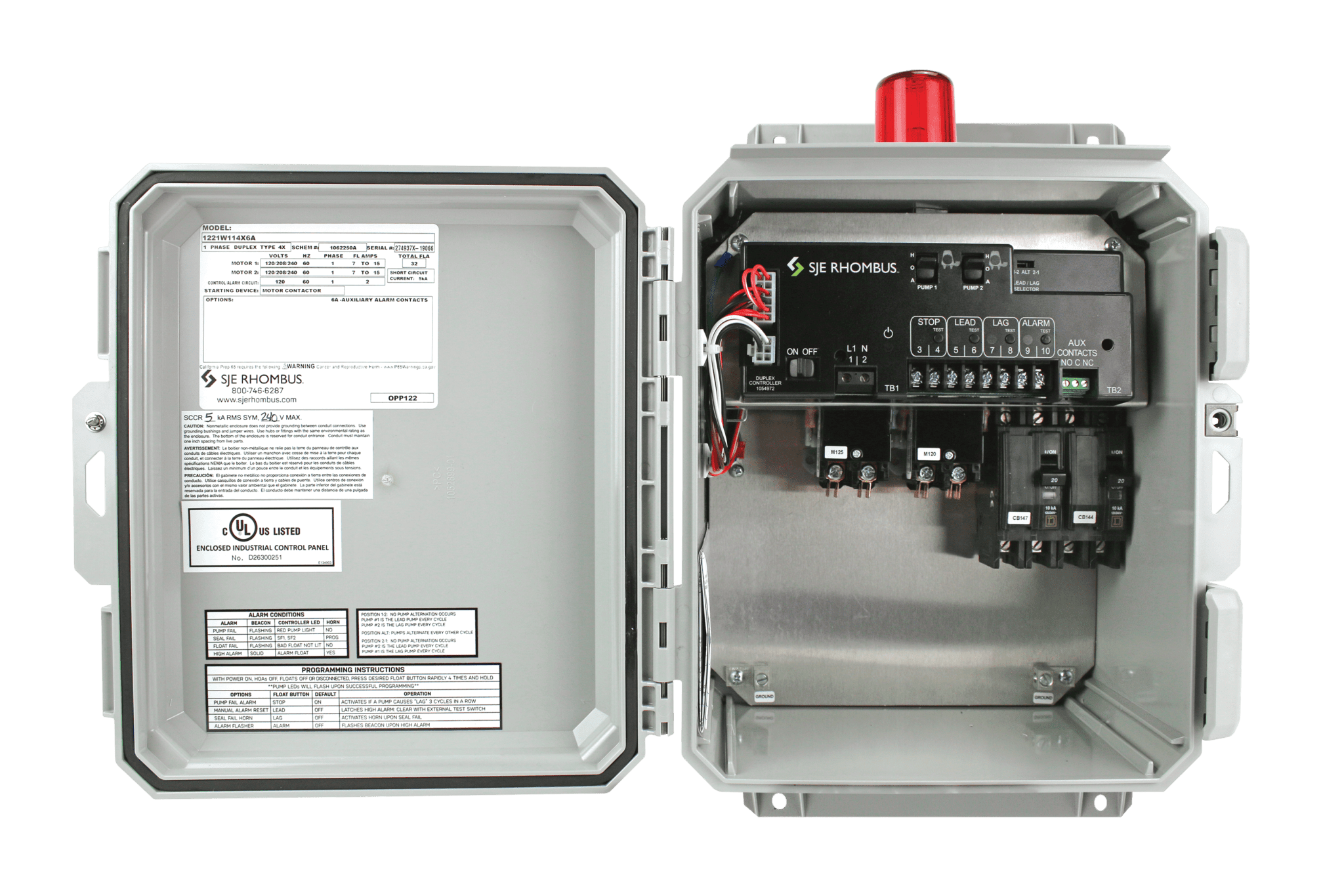
Model 122 Sje Rhombus Control Products

Duplex Alternating Starter Franklin Electric
Lead Lag Pump Alternation Control Precision Digital
Three Phase Duplex Demand Wd3p 4 Pump Control Panel See Water Inc

The Three Stages To Controlling A Chiller And Its Primary Secondary Pumps Engineered Systems Magazine
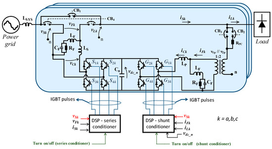
Energies Free Full Text Experimental Evaluation Of A Control System Based On A Dual Dsp Architecture For A Unified Power Quality Conditioner Html